Last updated on: November 25, 2025
Table of Contents
Introduction of Clash Detection
“Clash Detection” as the name suggests, it is about playing a “Detective” role and finding out clashes among trades in the virtual building design model. Any building design comprises mainly five trades/disciplines—Architectural, Structural, Mechanical, Electrical, and Plumbing. To give a simple analogy of a human body with respect to trades/disciplines – Architecture is the skin, MEP is the cardio-vascular system and Structure is the skeleton.
Just like in the human body, all the building systems have to function in-sync to achieve performance and functional expectations in terms of energy efficiency, sustainability, operational efficiency, etc.
Clash detection is very vital and no-brainer as it makes sure all the building systems are designed without any interdisciplinary conflicts.
BIM Coordinator in a company or in the project is responsbile for clash detection and associated processes and meetings. If you look at his/her role, it is like a Quality Inspector or Design Gatekeeper. A BIM coordinator makes sure that there are no clashes between any building disciplines and virtual building design is ready for construction.
In this blog, our goal is to explain and walk you thrrough clash detection through Navisworks in details (we really mean it!. have a cup of coffee for this 30-minute reading) alongwith the clash detection process.
So let’s get started and begin with understanding of clash detection and clash types.
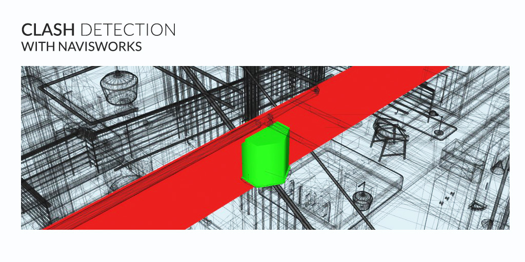
What is Clash Detection?
Clash detection is the method of identifying and inspecting the various building design interferences which frequently occur during the BIM coordination or Construction Gatekeeping process.
Clash detection is like a review process that ensures all building components, assemblies, and trades are in ready-to-be-installed conditions generating no conflicts with other building trades.
Clash detection will only come into the picture when all the building design trades (Architectural, Structural, Mechanical, Electrical, Plumbing, Fire Protection, and others) are integrated into the BIM model.
Types of Clashes
A conflict occurs when the elements of different MEPFP or other trades occupy the same space. This conflict can be geometrical (for example, HVAC crossing through structural beam), schedule-based (when the sequence of work is not as per the schedule or multiple things take place at once), or the changes are not updated in the drawings.
There are primarily 3 types of clashes:
1. Hard Clash
A hard clash occurs when two components of a building intersect or pass through each other.
Autodesk’s Navisworks is a BIM clash detection platform that identifies and resolves the hard clashes based on the geometric and rule-based algorithms embedded in the building design components.
2. Soft Clash
Soft Clash occurs when one element is not given the spatial or geometric tolerance and because of which its buffer zone is breached. It is a type of clash which gets flagged when a distance of less than a set tolerance is detected.
3: Workflow/4D
Workflow clashes, as the name suggests, are the timeline conflicts. They actually represent a mismatch in the scheduling of contractors or when there is a conflict of timeline with equipment or material delivery. It is knowns as 4D clash as it results from scheduling clashes that affect the efficiency of the entire construction firm.
It can bring construction activity on standstill as when one schedule gets interrupted it has a cascading effect on several other disciplines.
There are many Clash Detection softwares that are widely used by AEC fraternity such as Navisworks, BIM 360 Glue, Solibri Model Checker, Synchro Pro, Tekla BIMsight.
Top 10 Causes Of Clashes Found
During 3D Design Coordination

BIM | MEP | Virtual Design Coordination
Dashboard for Gatekeeper Meeting

Navisworks Overview
Autodesk Navisworks acts as a model aggregator as it brings together 3D models and associated design data into a single working environment for the purpose of design review, coordination analysis, simulation of the model, and presentation. There are many specialized tools in Navisworks such as Clash Detective, TimeLiner, Animator, etc. It allows an interactive review of the virtual project model in order to validate the design and provide accurate predictions for construction and operations.
Autodesk Navisworks’ greatest advantage is clash detection. It provides real-time collision detection during designing which gives the team clues to improve their design among multiple building systems and ultimately prevent costly remedies after drawing completion and during construction.
Additional Features:
- Navisworks Manage is a model aggregator that brings together 3D models and their associated design data into a single working environment.
- It allows design review, coordination analysis, simulation, presentation, and communication of design and constructability.
- It offers share view feature and users can review models on different platforms (Revit, Inventor, Rhinoceros, Solidworks, Sketchup, Allplan, Robot, CYPE, etc.)
- It offers a varied bucket of tools such as Clash Detective, Animator, TimeLiner, Quantification Workbook, etc.
Applications of Navisworks
- Clash Detection: It allows us to identify, prevent, and resolve conflicts in the virtual model before the actual start of the construction, and hence it reduces costs and schedule risks and minimizes proposed change order and RFI.
- 4D simulation: Autodesk Navisworks Manage allows simulation, coordination analysis, and manage changes that occur during ongoing construction by combining spatial coordination with construction planning.
Extensions of Navisworks
NWC
Cache FilesNWC files format is not intended for general use. It contains a cached version of the converted Revit model geometry. It allows users to open files into Navisworks which can be saved in NWF or NWD file format. NWC files are created to load the model more quickly when opened next. However, it does not allow users to save NWC file format.
NWF
Federated FilesAn NWF file contains data indexed data of all the model files that are being used. It stores all the other data opened in Navisworks. It is recommended to use the NWF file format while working with an ongoing project as any changes or updates made with the original drawings will get reflected in the next time the model gets opened in Navisworks.
NWD
CAD FileNWD files are lighter than CAD files (less loading time), and users can only save them if they have a licensed version. It is used to publish and share the compiled version of the ongoing project for others to review, even if they do not have Navisworks, they can use Freedom (free viewer). This allows the user to retain the source file and can share a secure NWD file.
BEP Tips for Clash Detection
When we talk about BEP in Clash Detection, we talk about a BIM execution plan which is a comprehensive document that covers and outlines all agreed processes and elements to collaborate in BIM. It is a document that also acts as a reference as it records protocols, roles, responsibilities, standards, Level of Detail, Scope of Work, data requirements, uses, and outcomes.
Tip 1: Model Requirements for Coordination
When it comes to the design coordination process, the most important aspect is planning. It is not as simple as it sounds, and we shouldn’t underestimate its complexity. In the BIM Execution Plan, we usually state who will model, what will be the content, and when it will get modeled. Level of Development (LOD) will describe the various levels at which the elements will be modeled throughout the project life cycle.
It is important to state the minimal size of the design drawing that is required to be modeled in BEP so that the models also have sufficient details that will be get analyzed in clash review. All the project teams should agree on the approach of modeling and provide their data so that it is accessible and operational for all.
Tip 2: Quality Control Check Plan
It is important to have a QC checklist or a plan which runs interference check and discovers the areas or elements that occupy the same space which will be part of the QC process to reveal the design conflicts beforehand. There are basic 4 checks required-
- Visual check- To ensure that there are no unintended models and the design intent is followed
- Interference check- It will detect problems in the model where two or more components are conflicting/clashing
- Standard check- to ensure that the project has followed the company standard in BIM
- Data Check- to ensure that the project data has no incorrect or undefined or duplicate elements. In addition, it will also ensure a reporting process if there is any conflict of the data provided and corrective action plans.
Tip 3: Coordination Analysis Strategy
In the planning process of BEP, the BIM manager and all other project teams should have an integrated coordination schedule with an analysis strategy for conducting clash detection and review.
Typically, clash review should be performed during major milestones of the construction activities
- Schematic Design stage (30%),
- Design Development (60%),
- Construction Documents (90%).
- Design-build projects may need weekly/biweekly review after 30%.
Tip 4: Clash Review Workflow
Clash Review of the building should have a systematic approach in order to create a productive workflow.
- Weekly or daily teams should conduct a Design Review with BIM Manager. The intension is to visually verify the design in Revit.
- Run a clash review session during milestones discussed above weekly or bi-weekly.
- Save all the clashes as Viewpoints in Navisworks and with NWD file to the team. NWD will provide an easy viewing facility in Navisworks Freedom (viewer).
- Publish the same clash report in HTML and then converting it in PDF format.
- Upload the clash review data to Common Data Environment for the different needs of the project team, manager, contractor and client.
Best Practices for Clash Detection in Navisworks
Tip 1: Set Clash Rules and Templates (search sets & selection sets)
It is important to set clash rules and templates as it will facilitate streamlining of the clash review process. One rule or one template may not be sufficient for all. Hence, it is essential to carefully check the results once rules and templates are integrated.
Follow the below steps to avoid clashes between two sets:
- Click on “New” to create a new rule
- From “Rule Templates” list below, select “Specified Selection Sets” and choose the required set from the “Rule Editor” drop-down menu
- After applying the clash result will show “Resolved” as the status in yellow color.
- Print the report data, if required.
Import & Export Clash Test as XML
Navisworks allows users to export or import clash report data in XML format, and with this, we can create a standardized clash review test for the entire project/company. We can reuse the same clash test procedure for the next task/project subject to the selection of the test.
Selection Sets vs. Search Sets
Selection Sets: are “static groups” of items. It involves some manually added “Hide Items” and can exclusively be used on the current project.
Search Sets: are “dynamic groups” of sets generated by “keyword search” in “Find Items”. Search Sets can be Imported or Export and can be reused for over one project.
Tip 2: Clash the BIG Stuff First and Reduce Tolerances in Steps
During the early phase of the project, this method can be very useful during the early phase of the project. It is important to make sure of the bigger things first and verify that they don’t clash. It may occur that an elevator can intersect with the staircase in the design. This method reveals the primary issues and that it required resigning instead of resolving the clashes. Many structural elements like tunnels, sewers, or existing foundation cannot be moved or modified, and if any clashes occur, other disciplines can be moved or altered more easily and cheaply.
Tip 3: Grouping the Clash Results
There are going to be many clash results, hence, it is important to group them in order to look more organized. The naming convention to follow should be according to the group. Then we can see the overall clash report view just be clicking the “group” in Navisworks. The name of the group should be concise by descriptive and should be uniformly followed by everyone.
Pipe_Steel Beam (note: Under “Process Mechanical vs. Structure” clash test, we name the clash group as “P’s sub-system vs S’s sub-system”)
Tip 4: Clash Report Formatting with your Company’s Logo
Many kinds of clash report formats are available in Navisworks. HTML is one of the nice formats to illustrate information in a tabular format within limited spaces. Navisworks allows different kinds of settings to reveal the data as user wishes to. Like we discussed saving all the clash report results as Viewpoints and share those results in NWD file format, user can easily replace the Navisworks logo with their brand’s name, logo, etc.
In addition, there is a “hidden” setting which changes the exported image data resolution and file format from the HTML format in the following steps:
- Click the Application Button (big green N).
- Hold down the Shift key, and then select Options.
- Browse to the Registry -> Clash Detection -> Reports node of the options.
- For Image Export, change to the desired image height and width.
- For Image Export Plugin change the value from lcodpexjpg (.JPG) to lcodpexpng (.PNG) if needed.
Tip 5: Switchback between Navisworks and Revit
- Open Revit in the same version you used for exporting out the NWC to Navisworks.
- Click on Add-Ins tab > External Tools > Navisworks SwitchBack to enable it.
- In Navisworks Manage, Clash Detective window, on the Results tab, click the SwitchBack button.
- Revit will load the relevant project, find and select the item, and zoom to it. If SwitchBack was unsuccessful with the selected object, and you receive an error message, try selecting further up the Selection Tree in Autodesk Navisworks.
- Note: If you try to use SwitchBack and the RVT file is not in the same location as when it was saved, a dialog box will appear asking you to browse to the RVT file. When using SwitchBack for the first time to load a Revit file, a 3D view based on the chosen projection view mode is created in Autodesk Navisworks. The next time SwitchBack is used to load a Revit file, the same projection view mode loads, unless the projection view mode is changed in Autodesk Navisworks.
Tip 6: Dynamo for Navisworks & Clash Sphere Generator Plugin
If a team member doesn’t have Navisworks Manage to use the SwitchBack function or to review he grouped clash results, the screencast link below will provide an alternative solution to use Navisworks Excel and Dynamo to represent clash positions in Revit
There is a Clash sphere Generator Revit Plugin by BIM One that performs the same function. It reads locations and creates clash spheres in Revit once the report is exported by Navisworks in XML format. Every sphere is associated with an identification number making it easier to track and solve using Revit schedules. This file can be a new linked RVT model for reference. The project team can then view and resolve all the conflicts/interference issues directly inside the discipline model.
There are several options available to find and resolve the interferences in Revit model:
- Visual checks in Navisworks Freedom, Simulate or Manage
- By Element ID search in Revit
- Use SwitchBack function between Navisworks and Revit
- By Dynamo Script exported from Navisworks clash result in XML + Clash Sphere dyn + Revit Family
- Or BIM One- Clash Sphere Generator plugin in Revit
Tip 7: Compare Two Versions of the Model
Navisworks allows users to compare different versions of the model but not many are aware of it. When working with a BIM project, there are multi-disciplinary teams working and there are possibilities of many possible updates. Any change in the model file might get notified, but it may not possible to see what might have changed. The Compare Tool in Navisworks enables the user to look for differences in any two differences- can be files, layers, groups, or just geometry.
To compare two versions of the model:
- Open the first file that you want to compare in Autodesk Navisworks.
- Click on Home tab > Project panel > Append drop-down > Append, locate the second file, and click Open.
- Hold down CTRL key, and select both the files in the Selection tree.
- Click on Home tab > Tools panel > Compare.
- In the Compare dialog box, the Find Differences In area, select the check boxes for all the required options.
- After the comparison, the results will be highlighted in the Scene View.
The following color-coding is used by default:
Original Colors: Matched items
Red color: Items with differences
Yellow color: The first item contains things not found in the second item
Cyan: The second item contains things not found in the first item
Tip 8: Selection Inspector & DataTools
To enable external database in Navisworks, follow the below steps:
- Select the required elements using the predefined “Sets” and Open selection inspector
- Using “Quick property definition” have the properties added that needs to be exported out. Make sure you have the property>GUID added
- Use the export to CSV option from top right in selection Inspector
- Open CSV and add additional Properties/columns & save as XLSX.
- Open “Data Tools” form “Item Tools” ribbon
- Create new DataTools Links
- Select ODBC Driver – Microsoft Excel Drivers. For Setup – select the XLS just saved.
- For SQL setup: SELECT * FROM [name of XLSX$] WHERE “GUID”=%prop(“Item”, “GUID”)
- For Fields: add in the column names exactly as in excel and then save and close
- Now when in Navisworks as you select the actuator you should be able to see a new tab “Actuator Data” listing all the properties from the Excel file. When you publish NWD to BIM 360 Glue, the info gets carried along!
Tip 9: Visualization (A360 Cloud Render & Ray Trace Rendering)
The rendering option is available using Autodesk 360. These are in the cloud and are faster to use and offer many varieties- panoramic view, still image, interactive panorama, color-coded illuminance, lighting analysis, stereo panorama, etc. user can easily access it by scanning the QR code or by sharing the URL with the client.
Viewpoints (with daylight or interior lights) can be rendered “on the cloud”, and files that are stored can be reviewed on the Render Gallery. Once the task is completed, the user will receive an email. Submit a view and continue to work. Images can also be downloaded if local copies are required.
Tip 10: Quantification
Quantification is another core feature of Navisworks where the user can create a highly accurate quantity takeoff based on the access to multiple 3D source files. It also works with 2D takeoffs from DWF sheet sets. For more details on quantification, follow the below link:
Tip 11: BIM 360 Glue Shared Views with Navisworks
Real-time BIM collaboration is one of the major features of Navisworks since 2016 version. Navisworks allows users to open, append and align BIM 360 glue project models which can then be saved as a merged model. As soon as the model gets saved in Navisworks, it is available in the cloud for project review, collaboration, and design coordination. One can open models from BIM 360 Glue and use different tools such as the enhanced quantification features or enhance quantification features in Navisworks.
Below two products have distinct strengths that meet the requirements of different project participants:
BIM 360 Glue: It is a cloud-based coordination and collaboration solution that connects the entire project team– internal and external, and streamlines the project review workflows.
Navisworks Manage: A feature-rich BIM project review platform for heavy users to help perform advanced clash detection, quantification, 4D/5D analysis, and construction simulation.
| Features | Navisworks | BIM 360 Glue |
| Federated Models | Yes | Yes |
| LMV Navigation | Yes | Yes |
| 3D Coordination | Yes | Yes |
| Real-time Collaboration | No | Yes |
| Model Review | Yes | Yes |
| Clash Detection & Markups | Yes | Yes |
| Real-time Clash Notification | No | Yes |
| Timeliner Clashes | Yes | No |
| Quantification | Yes | No |
There is no option to group the clash results in BIM 360 Glue and any clash groups in Navisworks Manage cannot be direactly read in BIM 360 Glue. However, these is a workaround to take the saved clash groups as Viewpoints and “sync” them as share view in BIM 360 Glue by following the below steps:
- Open Navisworks
- Open BIM360 Glue model in which clashes will run
- Open Navisworks Clash Detective > Write Report > Report Format: As Viewpoints (include everything or group headers only)
- Open BIM 360 Share Views from Navisworks BIM 360 tab
- Highlight the “Group Header” from the saved viewpoints.
- Click “New” in BIM 360 Share Views.
- Recommended to rename the shared view to be mode descriptive
Anytime a new Shared View is created, Navisworks “auto-synchronize” the vide back to BIM 360 Glue View > Shares Views even if the model isn’t saved. Team will be notified vie email about the created new view. In addition, users can also use the markup tools if they want to add some comments or want to notify the project members about the project.
Integrate Navisworks & BIM 360 Model Coordination for Issue Tracking and Automated Clash Detection
With integrated use of two big platforms- Navisworks and BIM 360 Model Coordination, we’re bring best of both the products.
Time-saving and Cloud capabilities- This integration allows project teams to save time with automated clash detection, better quality of models, single source of truth and better issue management across the entire project team.
This feature enables traceability easier by the BIM manager to resolve all conflicts within Navisworks and in empowering coordination process. This represents an entirely new way to manage the model coordination workflow. It has opened up many possibilities like:
- Create and assign issues directly from Navisworks
- Save time with automated clash detection in BIM 360 Model Coordination
- Maintain a common data environment for the entire coordination process
The Benefits of the Navisworks Issues Integration
There are many ways in whcih Navisworks Issue Integration can help project teams:
- Ability to involve more people- More eyes on the models results in increase in the quality of models, lower cases of rework, saves money and improves scheduling.
- Provides a unified platform- It provides data in a common data environment, which connects the entire project team within a single solution.
- Easier issue tracking- It has made issue tracing convenient and transparent, ensuring resolution and requirement of collaboration if clashes occurs.
- Time-saving and less laborious: Automated clash detection in BIM 360 Model has reduced the laborious work of manual check for clashes. It saves time and empowers all the trade partners to self-check with using their models.
“By using the integrated processes of Navisworks and BIM 360, all project stakeholders from the field to the office are able to participate in issue tracking and resolution throughout the project life cycle. Using the BIM 360 Issues plugin in Navisworks, model coordination may now become a full-team effort, providing accessibility to team members that do not have experience in clash detection and navigation of models. Additionally, this transparency provides value to our clients, allowing them to easily harness the power of the model and truly understand project design, model development, and issue resolution.”
– Brian Popis, VDC Engineer II at Barton Malow
Navisworks Issues Integration: Key Features
- Model Coordination Automation- As design team and MEP teams share models to the shared spaces for coordination, the model automatically checks for current or potential clash issues.
- Collaborative Workflow- Review of all the multi-disciplinary models for making it construction-ready is possible as teams can create, assign issues and track through resolution in Navisworks or Model Coordination.
- Use if BIM 360- Use of BIM 360 in Navisworks allows the accessibility of content views from Model Coordination. It also ensures that users are working on the same content in Navisworks as in Model Coordination
- Different Clash Setups- It allows Naviworks to run and save clashed tests against BIM 360 Model Coordination managed datasets.
- Review Group Clashes and issue Screenshot- The user can review individual as well as group clashes in Navisworks and it can also be tracked with the attached screenshot.
- 4D Simulation– Navisworks allows users to leverage all the tools, including 4D simulation, depending on the design data.
- NWF- Use of NWF files with other users enables referencing, and content management via Model Coordination.
“Having Navisworks connected to BIM 360 allows us to manage our model reviews more effectively through issues in a common data environment. Additionally, by connecting Navisworks to the cloud we can integrate of the best of both Navisworks and Model Coordination workflows. This allows us the flexibility to utilize different processes to provide the best solutions for our clients.”
– Nick Bobbit, VDC Manager at Barton Malow
Challenges and New Opportunities
1. Cut Openings
Based on my clash review experience, “cut openings” is the number one common clash result generated by Navisworks because we normally don’t model the holes for pipes and conduits penetrating the concrete slabs and walls. Depending on the project BIM Execution Plan’s agreement, typically we don’t specify the openings for any pipes under a 3” diameter. However, these clashes impact not only material takeoffs but also structural calculations as well. With this in mind, we should carefully check every place where ducts, pipes, cable trays, or conduits meet building elements such as walls, floors, ceilings, roofs, beams, etc.
2. Parallel Clashing between Objects (“half-embedded”)
Parallel clash is to describe the situation where pipes are not embedded inside of the concrete through the wall or floor. usually, elements like pipes are placed on the wrong level. The parallel clash will help the user to review all such clashes once by clicking the group header either from the clash detection window or from the saved viewpoints in Navisworks. This will enable the associated team of engineers to review and make a decision to move the clashed items.
3. Egress Path 3D Checking
FLS- Fire, Life, and Safety in drawing sheets can often differ from the actual final design plans. Some architects treat the FLS sheets as “diagrams” just to meet the minimum code requirements for getting the permit. Egress Path 3D checking in Revit is intended to provide provisions, an automated technique that allows compliance checks to be carried out.
4. Model not based on the Specs or Fabrication Details
At times clashes can occur in some detailed area and its verification cannot be 100 percent valid as it might not be based on the specs with the fabrication details like shop drawings. It can be very common in a design-bid-build project delivery. Hence, it is important to keep some contingency and must not put objects tightly, or rely on the contractor to deal with that on the site.
5. Issue Tracking
Issue tracking can be difficult to handle and can be very challenging as Navisworks can enable clash detection but it may not be very easy to resolve the conflicts among the disciplines in a timely manner.
6. Unusual Behavior & Workaround
While exporting data into Revit to Navisworks, the model elements like size and shape might change. Sometimes it’s enlarged or minimized or gets totally changed in geometry or element ID. These issues need to be paid more attention especially when we involve complex projects.
7. Autodesk Point Layout within Navisworks
Autodesk’s Point Layout can help the construction team to bring greater model accuracy to the field. It is a construction layout software and it is ideal for those who need to conduct a layout on their job site. It creates points on every required element and export point location to a local station. This assures quality to and makes sure the element is installed as per the coordinated model. Add-on can be used to add on more control points & export it to a CSV or directly to BIM 360 Field.
How to Generate a Clash Report Using Navisworks
Clash Report Generation- Step 1
Autodesk Naviswork helps to generate clash reports between design models. The very first step is to upload the existing design model of one discipline into Navisworks software. Any two design models can be chosen to generate possible clash between the coordinated model.

Clash Report Generation- Step 2
Secondly, load the second design model which needs to be coordinated with the first independent model. The two separate models are combined in a single model in Navisworks for the further clash detection process.

Clash Report Generation- Step 3
The next step is to start the clash detection process by choosing the two models from the loaded model in Navisworks. Then come naming the report and running the clash detection test.

Clash Report Generation- Step 4
After running the scan, the system gives us all the potential clash between those models with status details, description and condition according to their level. It provides its status as new, active, approved and resolved which is essential when re-running the test after design alteration.

Clash Report Generation- Step 5
Lastly, when the clash report is generated, we will be able to choose file formats like HTML, PDF, etc. Clicking “Write Report” would generate a detailed report and individual images showing clashes. We can choose all the elements we want in the report.

BIM Clash Detection Reports

Plumbing to Structural Discipline

Mechanical to Structural Discipline

Electrical to Structural Discipline

Plumbing to Mechanical Discipline

Mechanical to Electrical Discipline

Plumbing to Electrical Discipline
Conclusion
All of this can seem like a lot to tackle. But you don’t have to take on all of these tasks at once, and you don’t have to do this by yourself. Work through these steps slowly, or work with experts to improve your clashes more quickly.
Working with United-BIM will provide you peace of mind because our experts will take care of all construction gatekeeping services including BIM Coordination and Clash detection, 4D Scheduling, and others.
About the Author

Coordination Manager / VDC Manager at United BIM
With over 10 years of experience in the AEC industry, Akash Patel is a seasoned Coordination Manager and VDC Manager at United BIM. His expertise lies in managing complex MEP-FP coordination projects and leveraging cutting-edge BIM technology to ensure seamless collaboration and precision. Akash is dedicated to delivering high-quality, detailed models that meet the demands of modern construction. He is passionate about optimizing workflows and driving innovation within the BIM field.