Last updated on: January 2, 2025
Table of Contents
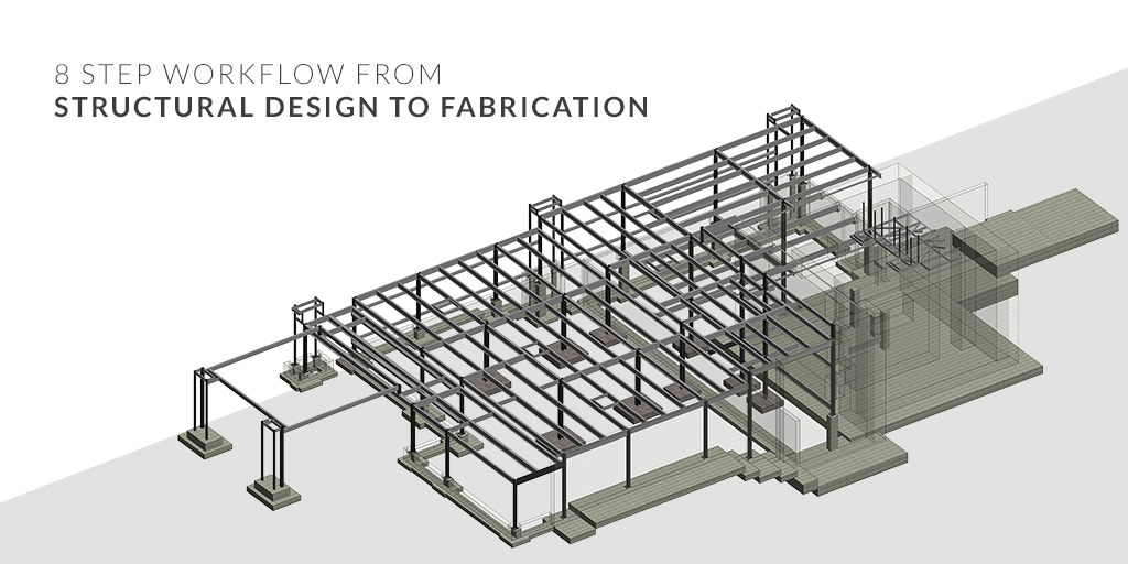
At first glance, it might seem that structural engineers are just professionals whose job is to design the structure of a building or a project, perform series of mathematical calculations about the strength and resiliency of a built structure, but it’s more than that. Structural Engineers design, manage design changes and updates daily. Coordinating the design models and drawings while maintaining the quality is a challenge structural engineers face daily. With keeping this in mind, we will explore connected Structural BIM workflow between Revit, Robot Structural Analysis (RSA), and Advance Steel to help Structural Engineers with their modeling efforts for drawings, analysis, and fabrication detailing.
We will understand structural workflow between:
- Revit– To handle the analytical model
- Robot Structural Analysis– To bring analysis results in Revit
- Advance Steel– To create fabrication documents

Handling the Analytical Model in Revit
Step 1: Add Start & End Releases
In this step, open the structural model in the Revit. To start, add Start\End Releases to each analytical bar inside the analytical model. It is important to specify the degree of freedom at each bar end. For example, Structural Columns, Rafters, and Main Beams require being set with Fixed Releases and for Purlins and Bracings; they need to be set with Pinned Releases. To add the releases, follow the below steps:
- Open the Structural Model in Revit.
- Open the 3D view and open the Graphics Overrides dialogue to enable the Analytical Model Categories in the view and click Apply.
- In the 3D view, select the ‘Column’ from the A-7 grid section. Right-click on it and select ‘Select All Instances’ and then from the submenu, select ‘In Entire Project’.
- After this, select the ‘Analytical Columns’ from the drop-down menu.
- Open the ‘Properties’ menu, and go to the ‘Base Release’ and ‘Top Release’ and select the ‘Fixed’ option.
- Repeat steps 3, 4, 5, and 6 for Grid D, Rafters, Main Beams, etc.
- For Purlins, Repeat steps 3, 4, 5, and 6, but instead select the ‘Pinned’ option.
- Open the Analytical Model view and select the ‘Front view’ from the view section. Using the selection from bottom-right to top-left, select the ‘Vertical Braces’ from the right side of the view.
- Repeat the above step for the Horizontal Braces.
- Go to the 3D view, Save and Close the project.
Don’t have the time to read the whole blog, no worries you can download it and read it at your convenient time.
Step 2: Add Boundary Conditions in the Model
In this step, add boundary conditions at the bottom of the Column in the model. This step is very important as it will specify the support conditions of the structure of the building. Hence, adding boundary conditions is very crucial as every column of analytical nodes needs to be covered. Follow the below steps to add boundary conditions:
- Open the file in Revit.
- In the ’Analytical Model’ view and open the ‘Analyze’ tab, select the ‘Boundary Conditions’ icon.
- Select ‘Point’ in Boundary Conditions Type and in the properties drop-down menu select the ‘Fixed’ state. Click ‘Apply’.
- In the canvas, click on the bottom of every Column analytical Node from Grids. After this, click ‘Esc’.
- Open the Structural Plan and open the ‘Base’ view. Open the ‘Visibility/Graphics Overrides’ dialog and enable the Analytical Model Categories in this view. Switch on the ‘Analytical Nodes’ category and then click ‘Apply’ and then click on ‘OK’.
- Zoom in on the Grid. Repeat the step 3, 4 and for setting the boundary conditions.
- In the end, go to the ‘3D View’, Save, and Close the project.
Step 3: Add Load Information- Cases and Combinations
Loads in construction materials can easily lead to destruction if applied stresses become larger than anticipated, or dead loads unexpectedly become live loads. In this step, add Load Cases, Loads and Load Combinations to the project in order to assess the possible deformations and stresses in the design. Follow the below steps to add Loads- Snow, Wind, Dead, etc.
- Open the file in Revit.
- Open the ‘Analytical Model’ view and from the ‘Analyze’ tab. Select the ‘Load Cases’ icon.
- Create Load cases: Dead Load, MEP Load, Snow Load and Wind Load
- Create Line Loads for every Load Case on the Analytical Model and include the details in the properties menu, like Orient to, Uniform Load, Project Load, Forces, moments and Identify Data, etc.
- Inside the canva, select the ‘Loads’ icon and then click on the Hosted Line Load command. Click on the properties, and select the applicable Load Case and place of value. Click Apply and select each column, purlin or grid from the canvas. After finishing the selection, press Esc.
- Select ‘Load Combination’ and add three Load Combination and an Envelope inside the Structural Setting.
Collaborate with Robot Structural Analysis to Bring the Analysis Results in Revit
Step 4: Analyze the Structural Model in Robot and Visualize in Revit
In this step, we will transfer the Model made in Revit to Robot Structural Analysis, analyze the structural model, transfer the results back in the Revit and then visualize the whole structure or by the selection. Follow the below steps to analyze and visualize the structural model:
- Open the ‘Analytical Model’ view, select the ‘Analyze’ tab and from the drop-down menu, select ‘Robot Structural Analysis. Then click on the ‘Robot Structural Analysis Link’.
- In the dialog that opens, click on the ‘Send Options’ button.
- Verify and select ‘DL’ case that contains self-weight in the option. Press ‘OK’ to save.
- Click on ‘Send model’ in the direction of integration with Autodesk Robot Structural Analysis and select ‘Direct integration’ in the type of integration.
- Robot Structural Analysis software will import the model from Revit. Press on the ‘Calculations’ command on the taskbar.
- The robot will perform the calculation and will reflect it in the ‘Calculations Messages’.
- From the taskbar, click on the Revit icon, to bring the Revit model in front. Then from the ‘Analyze’ tab, click on the ‘Robot Structural Analysis’ drop-down menu and select the ‘Robot Structural Analysis Link’
- In the dialog box that opens, update the results of the calculations by selecting ‘Update model and results’ and ‘Direct integration’ options. Then import the analysis results from Robot by clicking ‘OK’.
- In the following dialog box, un-select the ‘Required reinforcement results package’ option.
- In the ‘Analytical Model’ view, open the ‘Visibility/Graphics Overrides’ menu, select the Analytical Model Categories, and un-select the ‘Structural Loads’ category. Press ‘Apply’ and then ‘OK’
- From the ‘Analyze’ tab, click on the ‘Results Explorer’ button.
- View the results for the Analytical model dialog, select the load case and for results for members, select the ‘Moments My’ option. Press ‘Apply’. In this step, the model will populate the moment diagrams on the strong axis of the beams for load combination.
- To disappear from the model, uncheck the ‘Moments My’ option and press ‘Apply’.
- In the canvas, select a rafter and a column, then select the ‘Moments My’ option and press Apply. The moment diagrams will be displayed only for the selected elements.
- Save and Close the project.
Integrate Structural Analysis Results in Revit Steel Connection Workflows
Step 5: Verify the Steel Connections in Robot
In this step, we will determine the maximum moment between the Rafters and Columns, find the associated Shear Force and Axis Force and design a Moment End Plate connection between the 2 members, using the code checking module inside Revit. Follow the below steps to verify the steel connections:
- Open the ‘Analytical Model’ view, select the ‘Analyze’ tan and open the ‘Results’ explorer menu.
- Go to the ‘Result Explorer’ menu, select the Load case. Press apply and search for the maximum moment on Y-axis, at the end of a rafter beam.
- Un-check the ‘Moments My \ MAX’ option from ‘Results Explorer’ and press ‘Apply’. Select the element and apply the load case.
- Un-check the ‘Moments My’ option and apply the Forces (Fx, Fy, and Fx) to show the diagram.
- Zoom in the 3D View and select the ‘Column’ and ‘Rafter’ from the intersection of grids.
- Click on the ‘Modify’ tab and the ‘Steel’ tab click on the ‘Connection Settings’ button.
- In the Structural connection Setting dialog, click on the entire button set and then click on ‘Add’. Click on ‘OK’ to save and close the menu.
- To verify the connections in the steel tab, click on the ‘Connection’ command. In the drop-down menu of Family Types, filter and select families structural families and press ‘Enter’ to create them.
- Using the Tab key, select the element and edit the setting of ‘Plate & Bolts’, ‘Stiffeners’, and ‘Welds & Holes’.
- Properties can also be checked using ‘Code Checking’ under ‘Properties’ in an element.
- Generate the report by clicking the ‘Report’ button. An HTML file will open containing details of the verification for the steel connection.
- Go back in Revit, close the ‘Steel Connection Detailed Parameters’ menu, and un-check the ‘Override by Instance’ option, and press ‘Apply’.
- Save and Close the project
Step 6: Propagate Steel Connections of the Project
In this step, we will create a Base Plate Connection at the bottom of a column, a double purlin splice plate connection between two purlins and a rafter and then we will populate the model with these structural connections using the ‘Propagate’ command. Follow the below steps to create connections:
- In the 3D view, go to the ‘Steel’ tab and click on the ‘Connection’ command.
- Create the Base Plate connection, edit the ‘Type Parameters’. Click ‘OK’ and then apply the changes.
- To propagate the Baseplate in the project, select the ‘Base Plate’ connection, right-click on it, and from the contextual menu, select the ‘Propagate Connection’ command. This command will propagate the connection type on all the columns with the same section and geometrical position inside the model.
- Similarly, follow step-3 to propagate Moment End Plate in the model.
- Create the Double Purlin Splice Plate connection and then propagate it in the project.
- Save and Close the project.
Collaborate with Advance Steel and Create Fabrication Documents
Step 7: Setup the Export Setting and Transfer the model to Advance Steel
In this step, we will set up the export settings in the Revit extension of Advance Steel and transfer the model to Advance Steel software to create fabrication data for the project. Follow the below steps to create fabrication details:
- Open the file in Revit.
- In the ‘Add-Ins’ tab, select the ‘Advance Steel Extension’ and click on the ‘Settings’ button.
- Inside the settings menu, add the location of the families.
- Check the ‘Exports grid’ and ‘Ignore beam cutbacks and extensions on export’ options.
- In the ‘Advance Steel Extension’ drop-down menu, click on the ‘Export’ button.
- Save the exported file.
- Open ‘Advance Steel 2021’ US Version, select the ‘ASTemplate.dwt’.
- Import the Revit file from the ‘Export & Import’ tab in a new drawing.
- Save and Close the file.
Explore in Depth: 3D CAD, BIM & VDC | Difference, Scopes and Applications
Step 8: Number the Model, Create Detail Drawings, NC and DXF files
In this exercise, you will learn how to automatically number the model using the “With Drawing Number” option, create detail drawings (Single Part and Assembly), explode drawings to DWG, plot drawings to PDF, create NC files, and DXF files.
- Open the file in Advance Steel
- Inside the ‘Output’ tab, select the ‘Numbering’. Inside it, create Single Part and Assembly drawings using Drawing Processes.
- For the ‘Output’ tab, use ‘Document Manager’ to open, view, and select the detailed drawings. Select the detail drawings and click on ‘Add to batch plot’. This action will copy the detail drawing in a new category. Right-click on ‘Batch plot’ and select ‘Choose a plotter’.
- In the ‘Plot Device’, select ‘PDF’ and click ‘OK. You can also print the batch plot by right-clicking on it. The detail drawings will be printed in PDF and will be saved next to the DWG model.
- Open ‘Document Manager’, select the detail drawings, and click on ‘Add to explode’. With this command, detail drawings will get copied to a new category called ‘Batch explode’ and you can select ‘Set-up the explode options’ and choose the version of the dwg files that will be created and also select the layer, color, and line type to which element will be exported.
- In the ‘Output’ tab, click on the ‘NC’ command to create NC files.
- In the ‘Output’ tab, click on the ‘DXF (All objects)’ command to create DXF files.
About the Author

Coordination Manager / VDC Manager at United BIM
With over 10 years of experience in the AEC industry, Akash Patel is a seasoned Coordination Manager and VDC Manager at United BIM. His expertise lies in managing complex MEP-FP coordination projects and leveraging cutting-edge BIM technology to ensure seamless collaboration and precision. Akash is dedicated to delivering high-quality, detailed models that meet the demands of modern construction. He is passionate about optimizing workflows and driving innovation within the BIM field.