Last updated on: April 29, 2026
Table of Contents
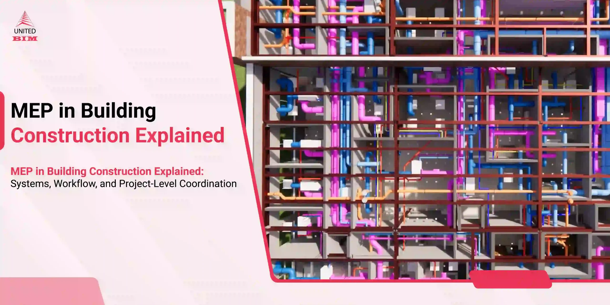
Picture this: Your electrical sub has run a full rack of cable trays through Level 3, only to discover on-site that HVAC ductwork already occupies that exact corridor. The mechanical crew isn’t moving their ducts. The electrical team isn’t moving their trays. Your project manager is now on the phone with three subs at once, and the schedule has just taken a two-week hit. Sound familiar?
This is one of the most recurring and preventable headaches in MEP construction across the United States. And yet, it keeps happening on job after job, even on projects that technically “used BIM.” The problem isn’t BIM itself. The problem is incomplete or siloed electrical coordination within BIM workflows, where each discipline models in isolation and nobody actually runs coordinated clash detection before it’s too late.
This blog is our attempt to lay out exactly how electrical BIM coordination, done properly, eliminates these clashes at their source and what that means for your project’s budget, schedule, and peace of mind.
Why Cable Tray and Conduit Clashes Are Such a Costly Problem
Cable trays and conduit systems are not forgiving when something’s in their way. They span long distances, require specific bend radii, need NEC-compliant clearances, and in many cases carry critical circuits that can’t just be casually rerouted. When they conflict with ductwork, structural framing, plumbing headers, or fire suppression mains, the resolution almost never happens quickly or cheaply.
30%
of construction rework stems from design coordination errors4-9x
more expensive to resolve a clash in the field vs. in the mode60%
more expensive to resolve a clash in the field vs. in the mode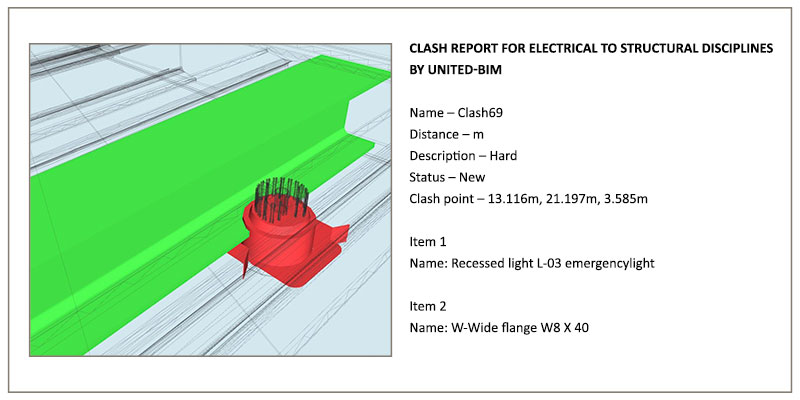
What Electrical BIM Coordination Actually Means
Electrical BIM coordination is the process of building a detailed 3D model of all electrical systems- cable trays, conduit, switchgear, panels, pull boxes, and equipment, and integrating it with every other discipline model in a federated environment to detect, review, and resolve spatial conflicts before construction begins.
That distinction matters. Having an electrical BIM model is not the same as having coordinated it. A model that exists in isolation, without being actively clash-detected against mechanical, structural, plumbing, and fire protection in a shared environment, gives you a false sense of security. Real coordination means all disciplines are in the same model, real conflicts are being surfaced and resolved, and the result is a routing plan every trade can build from without surprises.
Not sure if your current BIM workflow is truly coordinated?
Our team will review your process and tell you honestly where the gaps are.
Contact us nowHow Electrical BIM Coordination Resolves Clashes Before They Hit the Field
At a basic level, BIM coordination brings all trade models together, runs clash detection, identifies conflicts, and resolves them before construction. But in reality, the value lies in how those decisions are made.
For electrical systems, it is not just about detecting a clash, it is about understanding its impact. A cable tray cutting through a duct is a clear conflict. But a conduit running close to a structural member may or may not be an issue depending on installation methods, clearance requirements, and site tolerances.
This is where expertise matters.
Effective electrical BIM coordination requires understanding:
- Installation Practices
- NEC clearance requirements
- Support systems and spacing
- Real-world construction tolerances
Without this, teams either miss critical issues or generate excessive false clashes that slow down coordination.
150+
Electrical Clashes Resolved Before Installation150+
electrical clashes with structural systems were resolved before installation in this airport project.The Most Common Electrical Clashes We See
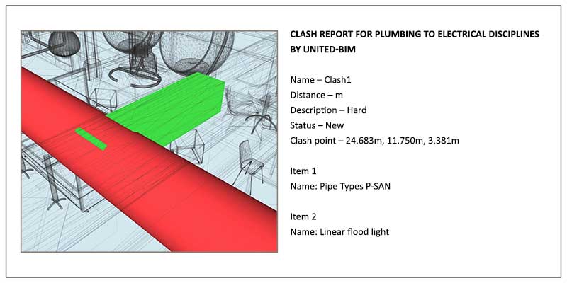
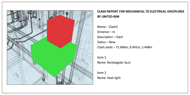
After coordinating electrical systems across hundreds of US commercial, healthcare, and industrial projects, here’s where conflicts show up most consistently:

Quick Insight
The most damaging clashes are rarely the obvious geometry hits. They’re the clearance and code-compliance conflicts that require domain knowledge to recognize as problems at all. Expert electrical BIM coordination catches both. Generic clash detection only catches the first kind.
The Step-by-Step Electrical BIM Coordination Workflow
A structured BIM coordination process is what ensures clashes are resolved before construction. If your current workflow skips these steps, that is usually where problems start carrying into the field.
All models including electrical, architectural, structural, mechanical, plumbing, and fire protection are reviewed for completeness and LOD compliance. Incomplete or low-detail models are flagged early to avoid misleading coordination results.
All discipline models are combined into a single federated model. Coordinate systems are aligned to ensure accurate positioning, as even minor misalignment can create false clashes and disrupt coordination.
Clash detection is configured using project-specific rules such as clearance requirements and system tolerances. Instead of broad detection, targeted rule-based checks are run to generate meaningful and manageable results.
Clash reports are filtered to remove duplicates and false positives. Remaining issues are categorized by severity and trade involvement, creating a focused list for resolution.
Each clash is reviewed with relevant disciplines. Responsibilities are assigned, and resolutions are tracked through a structured clash log until closure.
Once clash-free, coordinated drawings and models are finalized. A formal sign-off confirms all trades have reviewed and accepted the coordinated design as the construction baseline.
What Your Project Actually Gains
When electrical BIM coordination is done properly, the impact is felt across every dimension of project delivery. Field RFIs related to routing conflicts typically drop by 70 to 85 percent. Rework costs, which are always significantly higher than the cost of the coordination work itself, shrink dramatically.
For project owners, the benefits extend beyond delivery. A properly coordinated electrical model provides documented evidence of NEC compliance for working clearances and separation requirements, which is increasingly valuable during inspections and in any post-construction disputes.
At United BIM, our electrical BIM coordination services are built around these principles. We bring dedicated electrical BIM specialists who combine field-informed systems knowledge with deep technical BIM expertise. We’ve coordinated electrical systems across healthcare, data center, higher education, commercial office, and industrial project types across the US, and our coordination process is structured, documented, and proven at scale.
FILL OUT THE FORM AND WE’LL BE IN TOUCH SOON!
BIM helps electrical engineers validate routing, avoid clashes, and ensure systems are constructible. It reduces guesswork and improves coordination with other trades.
BIM tools like Navisworks use rule-based clash detection to identify geometric and clearance conflicts between electrical systems and other trades within a federated model.
Common tools include:
• Revit for modeling
• Navisworks for clash detection
• BIM 360 or ACC for coordination workflows
Ideally, coordination should begin during the design development or early preconstruction phase. Starting late reduces flexibility and increases rework risk.
Outsourced teams bring focused coordination effort, structured workflows, and experience across projects, helping resolve clashes faster and reduce downstream risks.
Yes. A 3D electrical BIM model is created from the 2D design drawings- often called contractor or shop BIM- and then coordinated against 3D models from other disciplines. The conversion adds time but is entirely standard. Frequently, building the 3D model surfaces design issues that weren't visible in the flat drawings.
The duration depends heavily on project size, model quality at the start, and the number of disciplines involved. For a mid-size commercial project, a thorough electrical coordination cycle typically takes four to eight weeks from initial model receipt to coordination sign-off, assuming reasonably complete input models and an engaged project team. Larger, more complex projects like hospitals or data centers may require three to five months of active coordination. These timelines should be built into the overall project schedule, not treated as a late addition.
About the Author

Coordination Manager / VDC Manager at United BIM
With over 10 years of experience in the AEC industry, Akash Patel is a seasoned Coordination Manager and VDC Manager at United BIM. His expertise lies in managing complex MEP-FP coordination projects and leveraging cutting-edge BIM technology to ensure seamless collaboration and precision. Akash is dedicated to delivering high-quality, detailed models that meet the demands of modern construction. He is passionate about optimizing workflows and driving innovation within the BIM field.