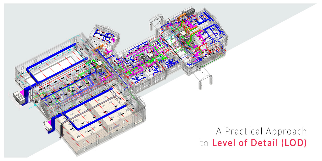
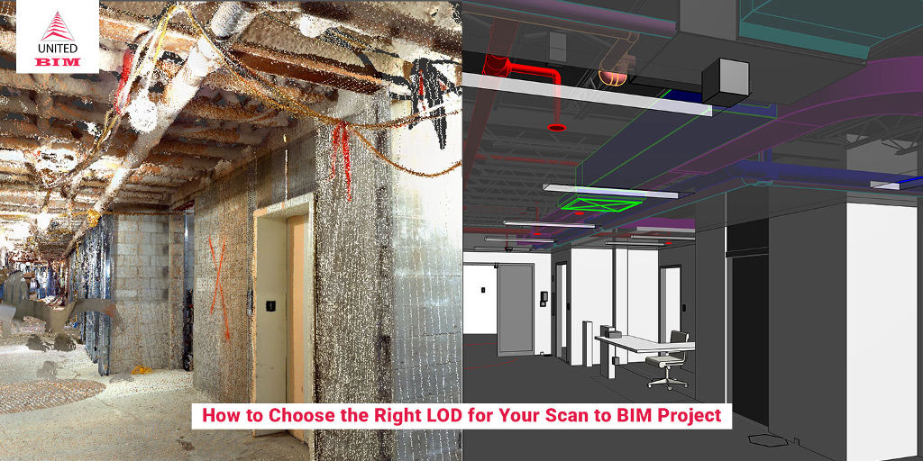
Last updated on: January 2, 2025
It is said that “Construction stops when languages are confusing”, very nicely described in an article by Redshift, Autodesk University.
In this Digital Age, we see the construction industry working its way through Building Information Modeling (BIM) as the detail level can range from a broad geometric representation to creating an accurate as-built model. For a project to execute successfully everyone must speak the same language. Because the difference in understanding is going to cause problems. It is very important to have a better way of communicating the requirements between Project Owners, Designers, Contractors, etc., and that better way is known as the BIM Level of Detail (LOD). LOD is a way where disciplines can communicate their requirements to one another.
The Level of Detail (LOD) is to define the amount and degree of building information that needs to be placed in a BIM Model. This not only includes graphical objects or physical characteristics but also the data associated with the objects. In short, Level of Detail (LOD) is a framework that is used to specify the development of the BIM Model and this helps in communication and coordination with all the project teams.
In this article, we will understand the levels and how they can be used as a basis for contract documents and a medium (language) to communicate the needs and wants.
The Six Levels of Detail in Project
The American Institute of Architects (AIA) established LOD in the year 2008 when it initially introduced five “levels of development” for defining the amount of detail about the BIM model. But later, to help the building trades adopt and implement them in a better way, BIMForum interpreted those levels for specific building components and published them in the year 2013 as Six Levels of Development (LOD).
These levels and features of building components and level of information at each LOD stage are described below:

Don’t have the time to read the whole blog, no worries you can download it and read it at your convenient time.
LOD 100 (Concept)

This is a conceptual level, where the model element is graphically represented with generic shapes and symbols. The element in the model might just be a block representing the project. It does not entail any typical shape or size.
At this level, spaces of the project are modeled as generic objects with approx. sizes, shapes, and location. This level is to gain an understanding of the design and the spatial requirement. Blocks or space objects are placed in a model either in a random manner for quantification or in a blocking and stacking process.
Elements modeling includes- Space objects based on the area requirement of the design.
Assumptions for structural elements are included such as architectural floor elements that contain a layer for assuming structural framing depth and other schematic elements that are not distinguishable by type of material.
It includes diagrammatic or schematic model elements where there is a conceptual/schematic layout or a flow diagram.
LOD 200 (Approximate Geometry)
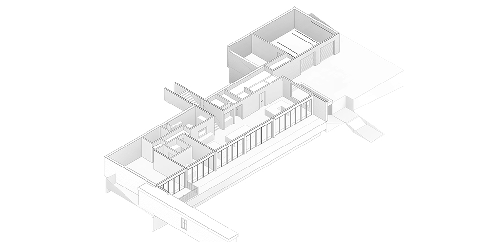
In this level, model elements are graphically represented within the model as a generic system, object, or assembly with approximate specifications, quantities, size, shape, location, and orientation. Any information derived from LOD 200 elements must be considered approximate. Non-graphic information may also be attached to the model element but it does not have any specific detail but it will present the geometry perfectly.
LOD 200 spaces are modeled with bounding elements such as walls, elevation, and columns. It defines the perimeter and area of spaces which is calculated with respect to the bounding elements. It includes vertical bounding elements and space objects that are associated with it.
Approximate size, shape, the thickness of foundation, slab, etc, Also it includes a floor plan with approx. dimensions, approx. supporting framing members and structural grids are defined accurately.
Schematic layout including generic model elements with approx. size, shape, and location of all the MEP elements.
It includes a schematic layout with approx. size, shape, and location of mains and risers and other equipment.
LOD 300 (Precise Geometry)
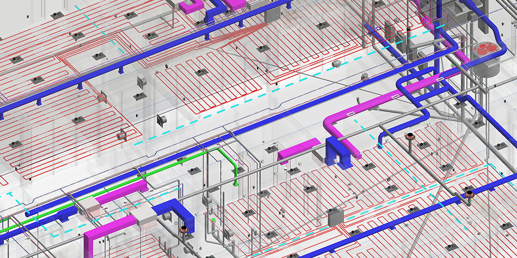
LOD 300 is similar to Construction Document (CD). It is a level where the model will contain accurate quantity, size, location, orientation, with detailing, fabrication, assembly, and installation information. Information contained by LOD 300 models can be used during the construction phase of the project.
All elements with the overall size, geometry, locations, and orientations of the structural element. It should include but not limit to defining material properties and finishes. Modeling should include sloping surfaces or floor depressions, main openings such as elevators or shafts, top, and size of pier, etc. External dimensions of the element should also be modeled.
Modeling of elements as per design-specified size, spacing, shape, and location of equipment/pipe/slope with given approximate allowances for spacing and clearance required for all specified anchors, supports, vibration, and seismic control that are utilized in the layout of the MEP equipment. Access/code clearance is required to model at LOD 300. For air distribution components, modeling of duct, dampers, fittings, insulation for risers, mains, and branches is required as per design-specified size, shape, spacing, and location of ducts.
LOD 350 (Precise Geometry with Connections)
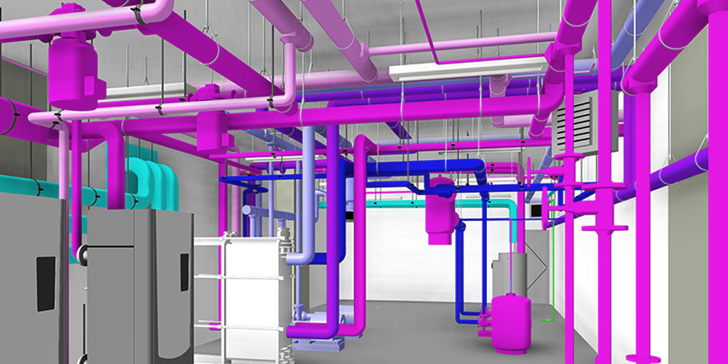
LOD 350 elements contain the same information as LOD 300, but they also include interfaces, supports, or connections with other building components. It displays how one system interacts with the other building systems.
It includes parts that are necessary for coordination between disciplines with nearby or attached elements are modeled. This will include items such as supports and connections. The quantity, size, shape, location, and orientation of the element as designed can be measure from the model without referring to the non-modeled elements such as notes or call-outs.
- Elements to a model under LOD 350 such as the location of sleeve penetrations, dowels, pour joints, chamfer, moisture retarder, dowels, expansion joints, all exposed embeds or reinforcements, the actual top of the pier, and expected to bottom of pier, dowel locations, water stops, void boxes, anchor rods, etc.
- It includes all penetrations to be modeled to rough opening dimensions, and any permanent forming or shoring components.
- For floor structural frame- actual elevation and location of member connections need to be modeled along with the main elements of typical connections applied to all structural connections like base plates, gusset plates, anchor rods, etc. It is important to model all the connection details and any miscellaneous steel members with the correct size, shape, orientation, and material.
- Erection details for installation, joist seat width, fire protection coating, non-standard joists seat depths and\or sloping joist seats must be included.
- Members modeled at any interface with wall edges (top, bottom, sides) or opening through the wall.
- Bridging or strapping components.
- LOD 350 models would include modeling of any regions that can impact coordination with other systems.
- Modeling of stair support elements are modeled (hangers, brackets, handrail connection points, etc.)
- It includes modeling of actual construction element size and shape, spacing, location/connections of plumbing components and equipment, slope of pipe, valves, fittings and insultation.
- Actual size, shape, spacing and clearance required for all hangers, supports, vibration and seismic control which are utilized in the layout of all the risers, mains and branches.
- Actual floor and wall penetrations to be modeled.
- Elements to be modeled at actual size, shape, spacing, and location/connection of equipment, ducts, dampers, fittings, and insulation for risers, mains, and branches/standpipes.
- It includes specifications with actual size, shape, spacing, and clearance required for all the supports, vibration, anchors, and seismic control that are utilized in the layout.
- Actual requirements of access/code in the model.
- Elements to be modeled as actual size, shape, spacing, and location of equipment and component associated with it.
- It includes actual size, shape, spacing, and location for supports and seismic control.
- Actual size, shape, and location/connection of equipment and support structure or pad elements.
- Actual requirements of access/code in the model.
LOD 400 (Fabrication)
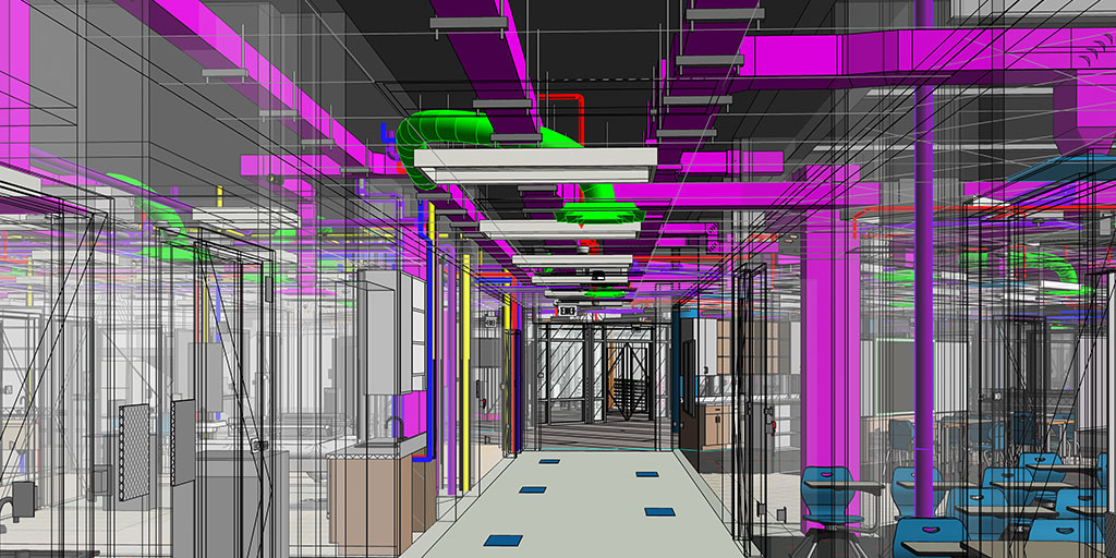
It is when complete fabrication and assembly information can be driven directly from the model. In other words, the details and information contained by LOD 400 elements can be handed over directly to suppliers to manufacture the building components being represented. Below is the recommendation of the elements that should be modeled at LOD 400.
For More Details, Read On: Do We Really Need LOD 400 for Everything? Or is it a Stretch?
- All elements including columns, beams, braces, gusset plates, connections, reinforcing plates and angles, pour stops, metal grating, seismic or secondary supports, and beam penetrations.
- The model will also contain non-graphic information that associates each element with its erection sequence as appropriate and identifies the size of the structural element.
- All the components are modeled at LOD 400 along with access zones, piping, fire pump, and sprinkler heads.
- All the equipment will be modeled with its overall height, width, depth, and point of connections along with modeling of equipment pads, inertial pads, pipe sleeves, and access panels.
- Pipe hangers and supports (including seismic bracing wherever applicable).
- All sleeves and penetrations through all walls, floors, slabs, beams, etc.
- Coordinates and sleeves locations and penetration with respective trades.
- All the plumbing, specialty piping, undergoing piping, and related accessories like valves, air vents, drain valves, flow meters, etc. should be modeled.
- Piping and process piping with ½” diameter or larger will be modeled with insulation wherever required. Hangers must be modeled wherever it is necessary to coordinate with the work of other disciplines.
- All equipment with its overall height, width, depth, and point of connections.
- Access zones for all the elements requiring access including but not limited to equipment fixtures, valves, and cleanouts.
- All equipment pads, inertial pads, pipe sleeves, and access panels.
- Pipe hangers and supports (including seismic bracing wherever applicable).
- Ducts, pipes, and related accessories. Hangers are modeled where it is necessary to coordinate with other disciplines.
- Access zones including but not limited to equipment, fixtures, standard dampers, fire dampers, VAV boxes, diffusers, turning vanes, filters, etc.
- All equipment pads, inertial pads, duct and pipe sleeves, and access panels. All equipment with its overall height, width, depth, and point of connections.
- All sleeves and penetrations through walls, floors, slabs, beams, etc.
- Model typical gages and piping setups for equipment.
LOD 500 (As-built)
This level of the model will have all the suitable geometry and information to support operations and maintenance of the building lifecycle. They have been completed and installed and their location has been field-verified and they constrain information clients can be utilized post-construction like model number, manufactured, dates purchased, and so on.
For operations and maintenance of the facility and spatial management, the following details are included in the model:
- Basic Information- system class, equipment name, developing BIM model of equipment, appearance description (word/picture), etc.
- Geometric Information- size, material, elevation, specific detail of the model (word/picture), etc.
- Maintenance Record- equipment resume, history records, checklist, record book of staff and schedule, etc.
- Equipment Detail Information- number, price, purchase date, specification, type, functions, unites, responsible person and units, brand/manufacture details, location, etc.
- Supplementary Information- warranty, assembly process, operation, manual, 2D manual, equipment performance table, manufacture information, etc.
Conclusion
LOD creates a standardized definition of what completion means and eliminates chances of discrepancies associated with project completion. Using LOD, teams working under different disciplines can communicate with each other in a better way with greater clarity. LOD enhances clarity in design by making use of advanced techniques and technology.
About the Author

Coordination Manager / VDC Manager at United BIM
With over 10 years of experience in the AEC industry, Akash Patel is a seasoned Coordination Manager and VDC Manager at United BIM. His expertise lies in managing complex MEP-FP coordination projects and leveraging cutting-edge BIM technology to ensure seamless collaboration and precision. Akash is dedicated to delivering high-quality, detailed models that meet the demands of modern construction. He is passionate about optimizing workflows and driving innovation within the BIM field.
